
FoilGrid GUI generates an O-grid, C-grid, or C-H grid for a single airfoil,
lets you inspect its quality, and exports a solver-ready CGNS or VTU mesh.
This manual describes the user interface, the airfoil .dat input format, and
the output conventions of the final mesh.
Contents
- Quick Start
- Airfoil DAT Input Format
- TE Closure and Topology
- Settings Panel
- Render Toolbar and Quality Inspection
- CGNS Output Conventions
- Logs and Problem Reports
1. Quick Start
- Open a
.datfile with Open Airfoil, or create an analytic airfoil with Create Airfoil…. - Select TE Closure and Topology to match the input trailing-edge shape.
- Set the required grid resolution and wall spacing, then click Generate.
- Inspect the grid lines and quality values. Invalid cells must be zero.
- Click Export Mesh… to save the mesh. CGNS is the default GUI output format.
Coordinate convention
Unit-chord coordinates with LE ≈
(0, 0)and TE ≈(1, 0)are recommended. FoilGrid does not automatically normalize or rotate coordinates loaded from a file.
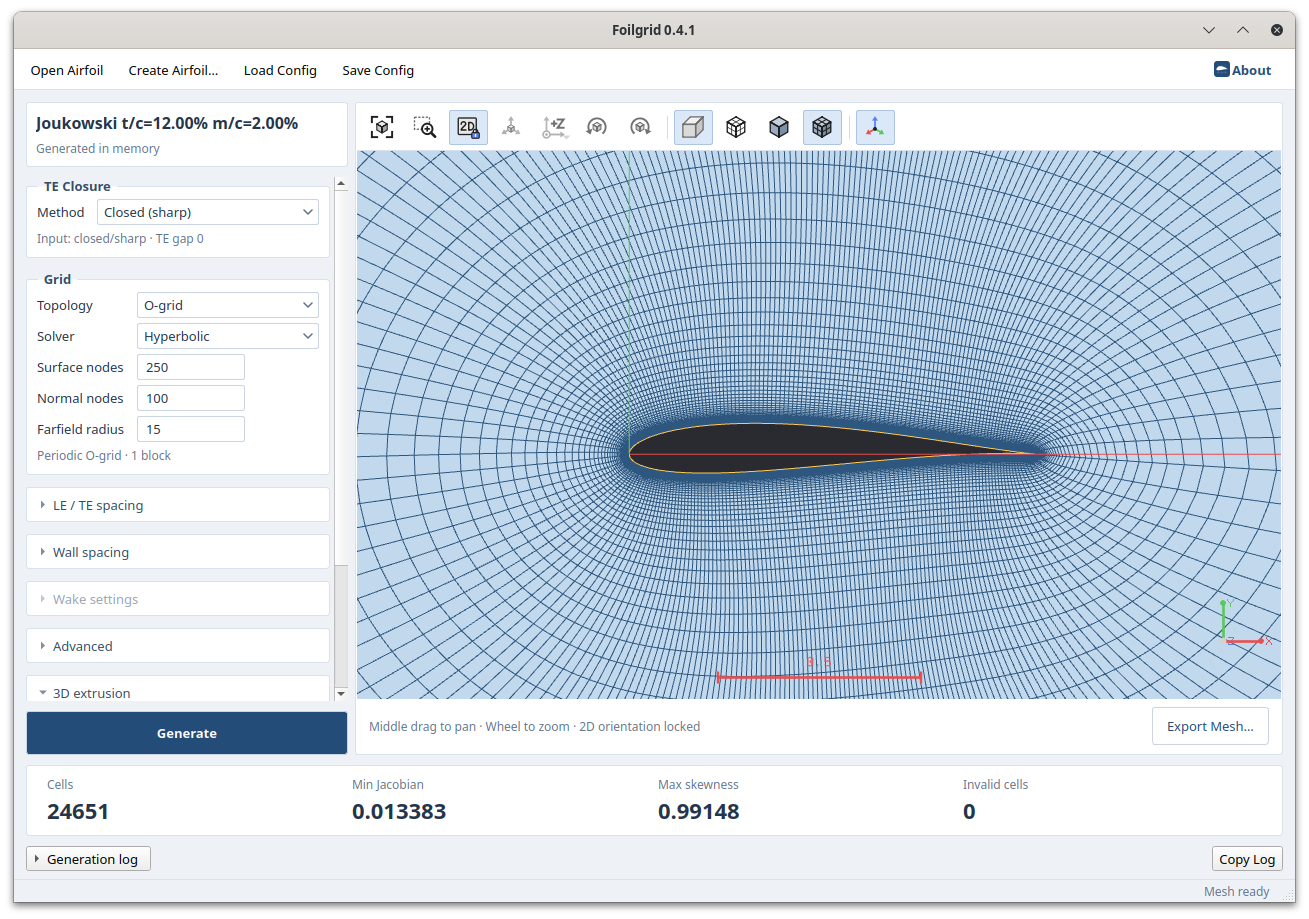
Use the left panel to define the geometry, grid, and wall-spacing settings, and inspect the generated mesh and quality in the center view. If you change a setting, the previous mesh remains visible but is marked stale. It cannot be exported until you generate the mesh again.
2. Airfoil DAT Input Format
FoilGrid reads the XFOIL/Selig labeled coordinate format. The first non-comment
line is the airfoil name. Enter whitespace-separated x y coordinates on the
following lines.
# Full-line comments are allowed
NACA 0012
1.000000   0.001260   # TE upper
0.750000   0.031600
0.250000   0.059400
0.000000   0.000000   # LE
0.250000  -0.059400
0.750000  -0.031600
1.000000  -0.001260   # TE lower
The recommended coordinate order is:
upper TE → upper surface → LE → lower surface → lower TE2.1 Supported Rules
- Spaces, tabs, and floating-point values in decimal or scientific notation are allowed.
- Blank lines and full-line or inline
#comments are allowed. - A reversed point order is corrected using a heuristic based on the Y coordinates near the endpoints.
- At least three points are required. At least 50 points are generally recommended for curvature reconstruction.
- The number of input points is independent of Surface nodes in the GUI. The input curve is reconstructed and redistributed to the requested number of nodes.
- The X-coordinate difference between the first and last points must not exceed
1e-9. An open TE may have different Y coordinates at the two endpoints, but their X coordinates must match.
2.2 Formats That Require Conversion
| Format | Required preparation |
|---|---|
| Coordinate list without a header | Add one line containing the airfoil name; otherwise, the first coordinate is consumed as the name |
| Lednicer format | Remove the upper/lower point-count header and convert the coordinates into one continuous surface list |
! comments | Replace them with # comments |
| Multi-element airfoil | The current GUI supports one continuous airfoil section only |
If the X coordinates of the two TE endpoints do not match, Generate is disabled and the GUI displays instructions for correcting the input. When converting an input file, follow the supported rules and coordinate order above.
3. TE Closure and Topology
| Input and closure | O-grid | C-grid | C-H grid |
|---|---|---|---|
| Open TE + Rounded | Supported, 1 block | Not supported | Not supported |
| Open TE + Flat | Supported, 1 block | Not supported | Supported, 4 blocks |
| Closed TE + Closed (sharp) | Supported, 1 block | Supported, 3 blocks | Interpreted as a C-grid, 3 blocks |
- O-grid: The simplest and most robust default. One periodic block surrounds the complete airfoil.
- C-grid: Creates grid lines extending downstream from a closed, sharp TE.
- C-H grid: Closes an open, blunt TE with a flat base and creates separate TE-base and wake blocks.
- Rounded: Connects an open TE with a curve. The GUI allows this closure for O-grids only.
O-grid and C-H Grid with the Same Flat TE
| O-grid | C-H grid |
|---|---|
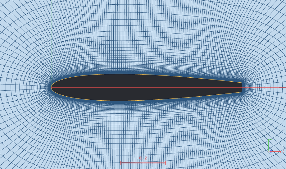 | 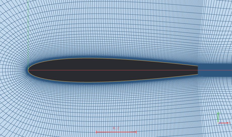 |
| One block surrounds the entire shape. | Separate blocks connect the TE base and wake region. |
O-grid and C-grid Examples by Solver
| Topology | Elliptic | Hyperbolic |
|---|---|---|
| O-grid | 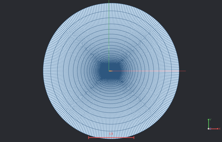 | 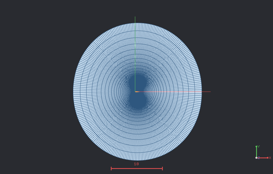 |
| C-grid | 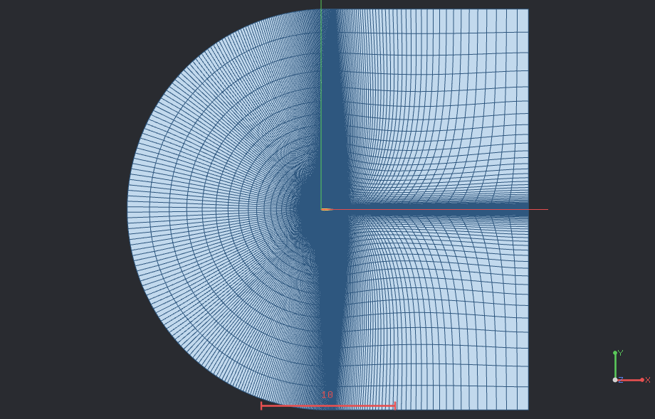 | 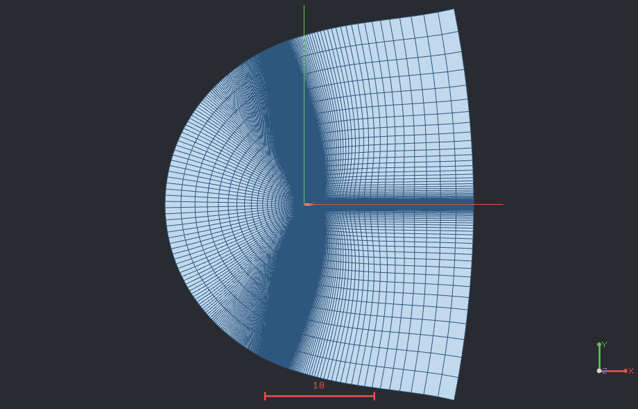 |
These figures illustrate how the outer boundary and grid-line distribution vary with solver and topology. The actual distribution also depends on the node counts, farfield size, wake settings, and Advanced options.
4. Settings Panel
The default values in collapsed sections are suitable for an initial grid in most cases.
4.1 TE Closure
| Item | Description |
|---|---|
| Closed (sharp) | Use for input with an endpoint gap of 1e-9 or less |
| Flat | Connect an open TE with a flat base surface |
| Rounded | Connect an open TE with a curve; available for O-grids only |
| TE gap display | Shows whether the input is open or closed and reports the actual endpoint distance |
4.2 Grid
| Item | Description |
|---|---|
| Topology | Select O-grid, C-grid, or C-H grid |
| Solver | Select hyperbolic marching or elliptic smoothing |
| Surface nodes | Number of nodes around the airfoil after closure processing; independent of the DAT input point count |
| Normal nodes | Number of wall-normal nodes, including the wall and farfield rows |
| Farfield radius | Size of the outer boundary in the input coordinate system |
4.3 LE / TE Spacing
| Item | Description |
|---|---|
| LE spacing | Surface-direction spacing at the leading edge; a smaller value clusters more points at the LE |
| TE spacing | Surface-direction spacing at the trailing edge; also used to determine the number of closure points |
When either value is zero, FoilGrid uses the automatically calculated value shown in the GUI. These values are spacings along the wall, not the height of the first wall-normal cell.
4.4 Wall Spacing
| Method | Input | Description |
|---|---|---|
| From y+ | y+, Reynolds, Reference chord | Calculate First height with a flat-plate correlation |
| First-layer height | Height | Enter the first wall-normal cell height directly |
The calculated First height appears below the settings. Reference chord and a directly entered Height must use the same length unit as the airfoil coordinates.
4.5 Wake Settings
| Item | Description |
|---|---|
| Wake nodes | Number of downstream wake nodes for C/C-H grids; not used for O-grids |
| Length factor | Length multiplier for the elliptic outer wake boundary |
| First-cell factor | First-spacing multiplier for the elliptic outer wake boundary |
Length factor and First-cell factor apply to the elliptic outer wake boundary. They are disabled for the hyperbolic solver.
4.6 Advanced — Hyperbolic
| Item | Actual role |
|---|---|
| Surface coupling (α) | Surface-direction coupling in the marching matrix; this is not a relaxation factor |
| Next-row smoothing | Reduces surface-direction irregularity in the displacement of the next row; its effect increases away from the wall |
| Current-row correction | Curvature correction for current-row coordinates; increasing it does not always produce a smoother grid |
| Outer-area uniformity | Blends the target cell area toward a uniform value near the farfield; a higher value preserves less surface clustering |
| Target-area passes | Number of neighbor-averaging passes applied to the target cell area at each marching step; it does not directly average coordinates |
| Block smoothing iterations | Elliptic smoothing budget after hyperbolic C/C-H blocks are connected; not used for O-grids |
4.7 Advanced — Elliptic and Output Cells
| Item | Actual role |
|---|---|
| Primary iterations | Initial elliptic iterations for an O-grid; included in the connected-block smoothing budget for C/C-H grids |
| Additional iterations | Additional smoothing after O-grid wall spacing is applied; added to the connected-block budget for C/C-H grids |
| Outer-boundary clustering | Circumferential distribution on an elliptic O-grid outer boundary; 1 is uniform and the option is not used for C/C-H grids |
| Triangulate (3D: prisms) | Split 2D quads into triangles, or 3D hexahedra into prisms |
Change Advanced values one at a time from their defaults, then compare the grid lines and quality values for the same input.
4.8 3D Extrusion
| Item | Description |
|---|---|
| Extrude to a 3D grid | Uniformly extrude the 2D mesh; generating a 3D grid automatically unlocks the 2D view |
| Length | Total extrusion distance |
| Divisions | Number of cells in the extrusion direction; the number of sections is Divisions + 1 |
| Rotate output to Z-up (+Y → +Z) | Rotate 90° about +X so the airfoil thickness direction, +Y, aligns with global +Z |
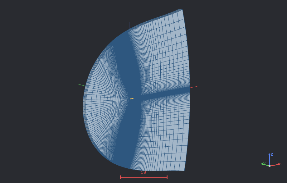
The figure shows a C-grid extruded to 3D with Z-up rotation enabled. The number of sections in the extrusion direction is Divisions + 1, and the two end sections are exported as symmetry markers.
LE/TE spacing, first-cell height, Farfield radius, and extrusion Length all use the same length unit as the input coordinates.
5. Render Toolbar and Quality Inspection
5.1 Render Toolbar
- 2D view: Locks the camera to a +Z parallel projection and disables rotation. Pan, zoom, and fit remain available.
- Surface: Shows cell faces only.
- Surface with edges: Shows cell faces and grid lines.
- Wireframe: Shows grid lines only.
- Direction, rotation, and parallel-projection controls become available after you turn off 2D view.
- Starting 3D generation automatically unlocks the 2D view.
5.2 Quality Values
| Display | Meaning |
|---|---|
| Cells | Number of cells in the final exported mesh |
| Min Jacobian | Minimum scaled Jacobian; it must be positive, and a larger value is better |
| Max skewness | Equiangle skewness in [0, 1]; zero is ideal |
| Invalid cells | Number of cells with non-finite values or a scaled Jacobian ≤ 0; this must be zero before export |
Do not rely on the numbers alone. Inspect the LE, TE, wake, and block interfaces for abrupt bends or sudden spacing changes. If invalid cells exist, the result remains visible for inspection, but Export Mesh… is disabled.
6. CGNS Output Conventions
CGNS is the default export format in the GUI, with VTU available as a secondary format. Interface nodes from the internal structured blocks are merged, and the final output is written as one unstructured zone.
| Item | Output convention |
|---|---|
| Mesh name | foilgrid |
| Zone name | fluid |
| Default 2D cells | QUAD_4; TRI_3 when Triangulate is enabled |
| Default 3D cells | HEXA_8; PENTA_6 when Triangulate is enabled |
| 2D coordinates | z = 0, cell dimension 2, physical dimension 3 |
| Block interfaces | Shared nodes are merged to form a continuous mesh in the final zone |
6.1 Boundary Markers and CGNS BC Types
| Marker | CGNS BC type | Creation condition and meaning |
|---|---|---|
airfoil | BCWallViscous | Airfoil wall in every topology |
te_base | BCWallViscous | C-H base surface for an open, flat TE |
farfield | BCFarfield | Farfield boundary, including the C/C-H outlet |
symmetry_low_z | BCSymmetryPlane | Start section of the default 3D extrusion, z = 0 |
symmetry_high_z | BCSymmetryPlane | End section of the default 3D extrusion, z = Length |
symmetry_high_y | BCSymmetryPlane | Start section after Z-up rotation, y = 0 |
symmetry_low_y | BCSymmetryPlane | End section after Z-up rotation, y = -Length |
FoilGrid provides boundary names and CGNS BC types; it does not assign the solver's physical boundary-condition values. Verify that marker names and BC types map to the intended conditions when connecting the mesh to a solver.
6.2 3D Coordinate Axes
- The default 3D mode uniformly extrudes the 2D grid in the +Z direction.
- Cell spacing is
Length / Divisions, and the number of sections isDivisions + 1. - With Rotate output to Z-up enabled, FoilGrid first applies
(x, y, z) → (x, -z, y)and then extrudes in the -Y direction. - In Z-up mode, the original +Y airfoil thickness direction becomes global +Z.
7. Logs and Problem Reports
The Generation log records:
- FoilGrid version, build type, Qt version, operating system, and CPU architecture
- Input shape name, path, coordinate count, chord, thickness, and TE gap
- Requested settings and the resolved topology, spacing, and grid dimensions
- Engine debug, info, warning, and error messages
- Block, node, and cell counts; quality values; and invalid-cell count
- Boundary marker names, CGNS BC types, and zone connectivity
- Export path, completion status, and file size
If you encounter a problem, click Copy Log in the Log panel and send the complete
contents to [email protected].
Anonymous usage statistics can be disabled in the About dialog. Telemetry includes only the product version and build, OS, CPU, memory, and generation success or failure. It does not transmit airfoil data, meshes, file paths, or settings.
Automation through the CLI program is available through a separate sales channel.
For customization or separate development, contact [email protected].
© 2026 CLEW, Inc. · Freeware · https://www.clew.tech