
1. Overview
BladeXtractor extracts profile (airfoil) point coordinates from 3D blade CAD files of axial compressors and turbines.
Use Cases
When working with turbomachinery blades, you often have a 3D CAD model but need accurate airfoil point coordinates:
- Reverse Engineering: Analyze existing blade geometry to extract design parameters or use as baseline data for new designs
- CFD Mesh Generation: Accurate blade surface point coordinates are required when generating meshes for computational fluid dynamics analysis
- Blade Design Verification: Verify that CAD models are generated according to design intent by examining cross-sectional shapes
- Software Integration: Transfer geometry data to other turbomachinery design/analysis tools
BladeXtractor automatically extracts airfoil sections at desired Span positions from STEP files and converts them into ready-to-use point coordinate data.
How It Works
- Load Blade STEP File: Load existing 3D blade geometry
- Load Hub/Shroud Curves: Define flow path geometry on the meridional plane
- Generate Stream Surface: Create revolution surfaces connecting Hub-Shroud at specified Span positions
- Extract Intersection: Calculate intersection curves between blade and stream surface
- Output Point Coordinates: Divide intersection curves uniformly and output 3D point coordinates
                          Shroud
                        ──
                       ╱  ╲
                      ╱────╲  ← Stream Surface (span=0.5)
                     ╱      ╲
                    ╱        ╲
              Hub  ╱──────────╲
                ← Z-Axis (Rotation Axis) →
Output Format
.curveformat compatible with Ansys® TurboGrid®- 301 points per Span (closed loop: TE -> LE -> TE)
- Hub/Shroud meridional curves (entire flow path range)
2. System Requirements
- Windows 10/11 (64-bit)
- Display: 1280x800 or higher recommended
Program Files
| File | Description |
|---|---|
bladextractor.exe | GUI application |
bladextractor-cli.exe | Command-line tool |
3. Preparing Input Files
3.1 Blade STEP File
- Format: STEP (*.stp, *.step)
- Coordinate System: Z-axis is the rotation axis
- Units: mm (millimeters)
Note: The blade must be a single blade. Full rotor/stator assemblies are not supported.
3.2 Hub/Shroud CSV File
Defines the radius distribution of Hub and Shroud on the meridional plane.
CSV Format:
z, r_hub, r_shroud
0.0, 50.0, 150.0
10.0, 52.0, 148.0
20.0, 55.0, 145.0
...| Column | Description | Unit |
|---|---|---|
z | Axial coordinate | mm |
r_hub | Hub radius | mm |
r_shroud | Shroud radius | mm |
Requirements:
- First row is header (ignored)
- Z values do not need to be sorted (auto-sorted)
- Z range must cover the blade Z range
CSV Scale Factor:
- Use when CSV units differ from blade units
- Example: If CSV is in meters (m) and blade is in mm -> Scale Factor = 1000
3.3 Flow Direction
Specifies which direction the flow travels along the Z-axis:
| Setting | Description |
|---|---|
+Z | Leading Edge at minimum Z (default) |
-Z | Leading Edge at maximum Z |
+Z Flow Direction:
    LE ------- Blade ------- TE
   Z_min                    Z_max
    <- Flow inlet           Flow outlet ->

-Z Flow Direction:
    TE ------- Blade ------- LE
   Z_min                    Z_max
    <- Flow outlet          Flow inlet ->
4. GUI Usage
4.1 Starting the Program
Run bladextractor.exe.
4.2 Interface Layout
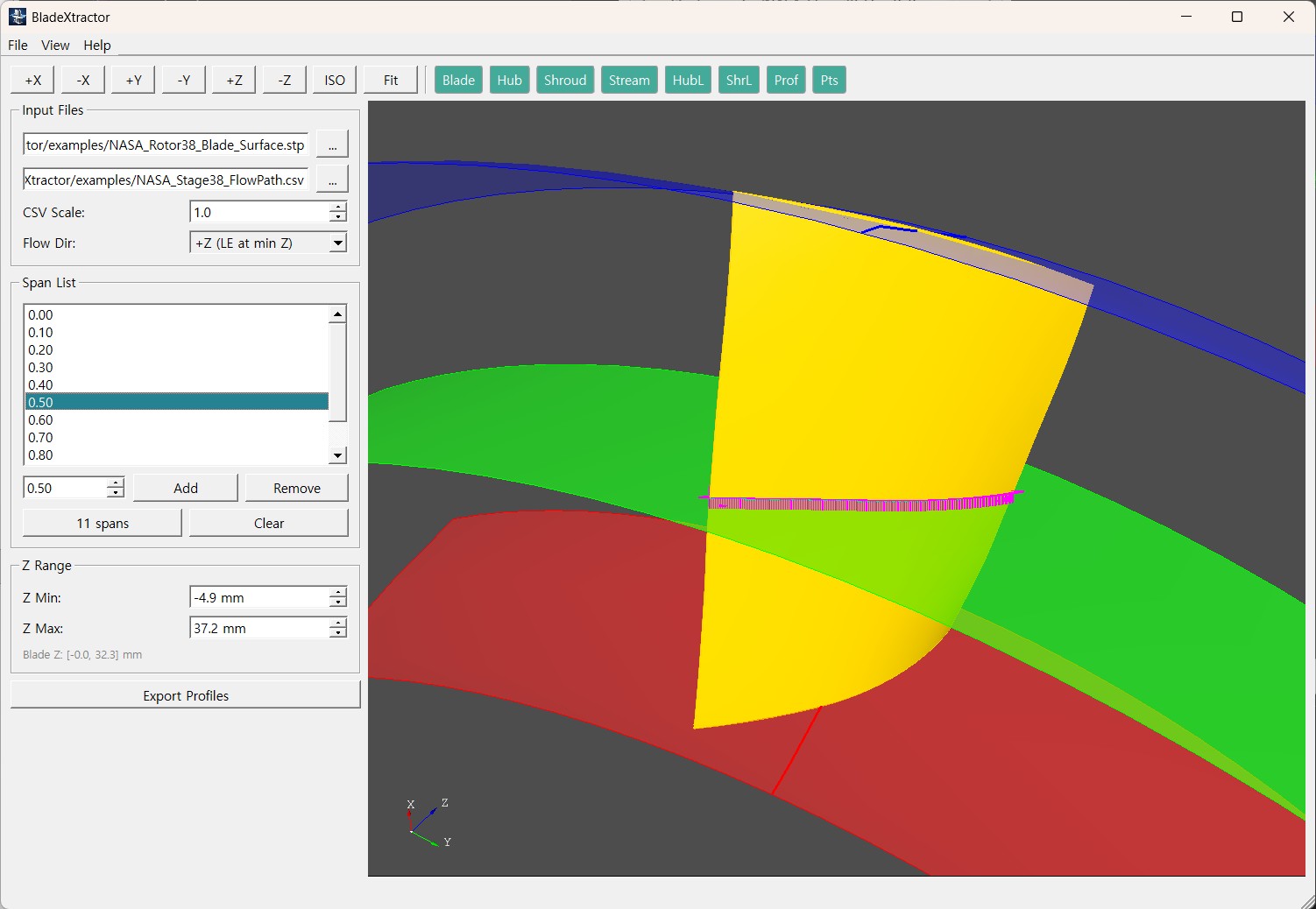
4.3 Basic Workflow
Step 1: Load Blade
- Click File > Open Blade... (or [...] button in left panel)
- Select STEP file
- Blade is displayed in 3D viewer
Step 2: Load Hub/Shroud CSV
- Click File > Open Hub/Shroud CSV...
- Select CSV file
- Hub (blue) and Shroud (red) curves are displayed
Step 3: Set Parameters
CSV Scale:
- If CSV units match blade:
1.0 - If CSV is in meters and blade is in mm:
1000.0
Flow Direction:
- If LE is at Z minimum:
+Z (LE at min Z) - If LE is at Z maximum:
-Z (LE at max Z)
Span List:
- Specify Span positions to extract (0.0 = Hub, 1.0 = Shroud)
- Enter value and click Add
- 11 spans button: Auto-add 0.0, 0.1, 0.2, ... 1.0
- Select item and click Remove to delete
Z Range:
- Blade Z range is displayed automatically
- Adjust manually if needed (match with Hub/Shroud curve valid range)
Step 4: Export Profiles
- Click Export Profiles button
- Select output folder
- Enter project name
- Progress is displayed
- Completion message shown
4.4 3D View Controls
Mouse:
- Left drag: Rotate
- Middle drag: Pan
- Wheel: Zoom
View Buttons:
| Button | Function |
|---|---|
| +X, -X, +Y, -Y, +Z, -Z | Standard views |
| ISO | Isometric view |
| Fit | Fit all |
4.5 Save/Load Configuration
File > Save Config...: Save current settings to JSON file File > Open Config...: Load JSON configuration file
Saving configuration allows batch processing with the same settings using CLI
5. CLI Usage
5.1 Basic Usage
bladextractor-cli.exe config.json5.2 JSON Configuration File
{
    "bladeStep": "blade.stp",
    "hubShroudCsv": "flowpath.csv",
    "csvScaleFactor": 1.0,
    "spans": [0.0, 0.1, 0.2, 0.3, 0.4, 0.5, 0.6, 0.7, 0.8, 0.9, 1.0],
    "flowDirection": "+z",
    "spanBoundaryMargin": 0.01,
    "zRange": {
        "auto": true,
        "marginPercent": 15.0,
        "min": 0.0,
        "max": 100.0
    },
    "output": {
        "directory": "output",
        "projectName": "MyBlade",
        "debugStep": true,
        "saveLog": false
    }
}
5.3 Configuration Options Detail
Input Files
| Key | Description | Default |
|---|---|---|
bladeStep | Blade STEP file path | (required) |
hubShroudCsv | Hub/Shroud CSV file path | (required) |
csvScaleFactor | CSV coordinate scale | 1.0 |
Span Settings
| Key | Description | Default |
|---|---|---|
spans | List of Spans to extract (0.0~1.0) | (required) |
spanBoundaryMargin | Hub/Shroud boundary margin | 0.01 |
spanBoundaryMargin: Prevents numerical errors at span=0.0 or 1.0. Example: 0.01 means span=0.0 is processed as 0.01, span=1.0 as 0.99
Flow Direction
| Key | Description | Default |
|---|---|---|
flowDirection | "+z" or "-z" | "+z" |
Z Range
| Key | Description | Default |
|---|---|---|
zRange.auto | Auto-calculate Z range | true |
zRange.marginPercent | Auto Z range margin (%) | 15.0 |
zRange.min | Manual Z minimum (when auto=false) | - |
zRange.max | Manual Z maximum (when auto=false) | - |
auto=true: Auto-calculate by adding marginPercent to blade Z range auto=false: Specify min/max values directly
Output Settings
| Key | Description | Default |
|---|---|---|
output.directory | Output folder | "output" |
output.projectName | Project name | STEP filename |
output.debugStep | Output debug STEP | true |
output.saveLog | Save log file | false |
5.4 Execution Example
> bladextractor-cli.exe config_rotor.json

[info] BladeXtractor v0.5.0
[info] Config loaded: config_rotor.json
[info]   Blade: NASA_Rotor38.stp
[info]   CSV: FlowPath.csv
[info]   Spans: 11
[info]   Flow direction: +z
[info] Loading blade STEP file...
[info] Loading hub/shroud CSV...
[info] Processing span 0.00...
[info] Processing span 0.10...
...
[info] Profile extraction complete.
6. Output Files
6.1 Output Folder Structure
output/
+-- MyBlade.curve          # Blade profiles (all Spans)
+-- MyBlade_hub.curve      # Hub meridional curve
+-- MyBlade_shroud.curve   # Shroud meridional curve
+-- MyBlade_debug.stp      # Debug STEP (optional)
+-- MyBlade.log            # Execution log (optional)
6.2 Blade Profile (.curve)
## Blade profiles   MyBlade
# Section no.  1
    1.23456789E+01    6.78901234E+01    1.11111111E+02
    1.23556789E+01    6.78801234E+01    1.11121111E+02
    ...
# Section no.  2
...Format:
- Header:
## Blade profiles - Section header:
# Section no. - Coordinates: X, Y, Z (scientific notation, tab-separated)
Characteristics:
- 301 points per section
- Closed loop: first point = last point
- Point order: TE -> LE -> TE (counter-clockwise)
6.3 Hub/Shroud Curves (.curve)
    5.00000000E+01    1.23456789E+01    0.00000000E+00
    5.20000000E+01    1.23556789E+01    1.00000000E+01
...Format: X, Y, Z coordinates only (no header)
Characteristics:
- Approximately 229 points
- Theta distribution follows blade camber line
- Inlet/Outlet regions maintain TE/LE theta
7. Troubleshooting
7.1 "No intersection found"
Cause: Stream Surface does not intersect with blade
Solutions:
- Check if Z Range matches blade range
- Check if CSV Z range covers blade Z range
- Verify Flow Direction is correct
7.2 Profile Looks Abnormal
Cause: Flow direction or Z range setting error
Solutions:
- Change Flow Direction (+Z <-> -Z)
- Manually adjust Z Range
- Increase spanBoundaryMargin (e.g., 0.01 -> 0.02)
7.3 CSV Load Failure
Cause: CSV format error
Check:
- Column separator is comma (,)
- Header row exists
- Numbers have no unnecessary characters
7.4 Hub/Shroud Curve Looks Wrong
Cause: CSV Scale Factor error
Solutions:
- Check CSV units and blade units
- Adjust Scale Factor
8. Technical Support
- Developer: CLEW, Inc.
- Email: [email protected]
- Website: https://www.clew.tech
9. Disclaimer
License
This software is provided as Freeware and may be used free of charge.
Warranty Disclaimer
THIS SOFTWARE IS PROVIDED "AS IS" WITHOUT WARRANTY OF ANY KIND, EXPRESS OR IMPLIED. This includes, but is not limited to, the implied warranties of merchantability, fitness for a particular purpose, and non-infringement.
IN NO EVENT SHALL THE DEVELOPERS OR COPYRIGHT HOLDERS BE LIABLE FOR ANY DIRECT, INDIRECT, INCIDENTAL, SPECIAL, PUNITIVE, OR CONSEQUENTIAL DAMAGES ARISING OUT OF THE USE OR INABILITY TO USE THIS SOFTWARE.
Users use this software at their own risk and are solely responsible for all consequences arising from its use.
Trademark Notice
- Ansys and TurboGrid are registered trademarks or trademarks of ANSYS, Inc. or its subsidiaries in the United States and other countries.
- CLEW, Inc. is not affiliated with, sponsored by, endorsed by, or otherwise associated with ANSYS, Inc.
- All other trademarks mentioned in this document are the property of their respective owners.
Appendix A: Example Configuration Files
A.1 NASA Rotor 38
{
    "bladeStep": "NASA_Rotor38_Blade_Surface.stp",
    "hubShroudCsv": "NASA_Stage38_FlowPath.csv",
    "csvScaleFactor": 1.0,
    "spans": [0.0, 0.1, 0.2, 0.3, 0.4, 0.5, 0.6, 0.7, 0.8, 0.9, 0.95, 1.0],
    "flowDirection": "+z",
    "spanBoundaryMargin": 0.01,
    "zRange": {
        "auto": false,
        "marginPercent": 25.0,
        "max": 71.8,
        "min": -10.7
    },
    "output": {
        "directory": "output",
        "projectName": "Rotor38",
        "debugStep": true,
        "saveLog": true
    }
}
A.2 Simple Configuration (Auto Z Range)
{
    "bladeStep": "my_blade.stp",
    "hubShroudCsv": "flowpath.csv",
    "spans": [0.0, 0.5, 1.0],
    "output": {
        "projectName": "MyBlade"
    }
}