
UVSim3D's MPSS and MSSS models compared against the in-air fluence rate measurements of Liu et al. (2004). The same measurements with DOM alongside are in the model comparison document.
This document asks two questions separately: is the shape of the distribution right (measurement comparison), and is the number of watts right (power audit). A profile that overlays the measurements answers only the first, and says nothing about the second.
The case
The in-air measurements of Liu et al. (2004), Figure 7.
| Item | Value | Source |
|---|---|---|
| Lamp | Atlantic Ultraviolet, 16 W | paper p.401 |
| UVC efficiency | 41.35 % → 6.616 W at 254 nm | paper p.401 |
| Arc length | 28 cm | paper p.401 |
| Lamp diameter | 1.5 cm | paper p.401 |
| Quartz sleeve outer diameter | 3.7 cm | paper Figure 6 |
| Refractive index | air 1.0, quartz 1.52 | paper p.395 |
| Medium | air — no absorption (UVT = 1) |
Measurement lines run parallel to the lamp axis at radii of 5, 10 and 15 cm, spanning ±14 cm axially, taken with a spherical actinometer.
The absence of absorption is what defines this case. With no attenuation in play the result is set by geometry and refraction alone, and how each model represents the lamp shows through directly.
Result 1 — against the measurements
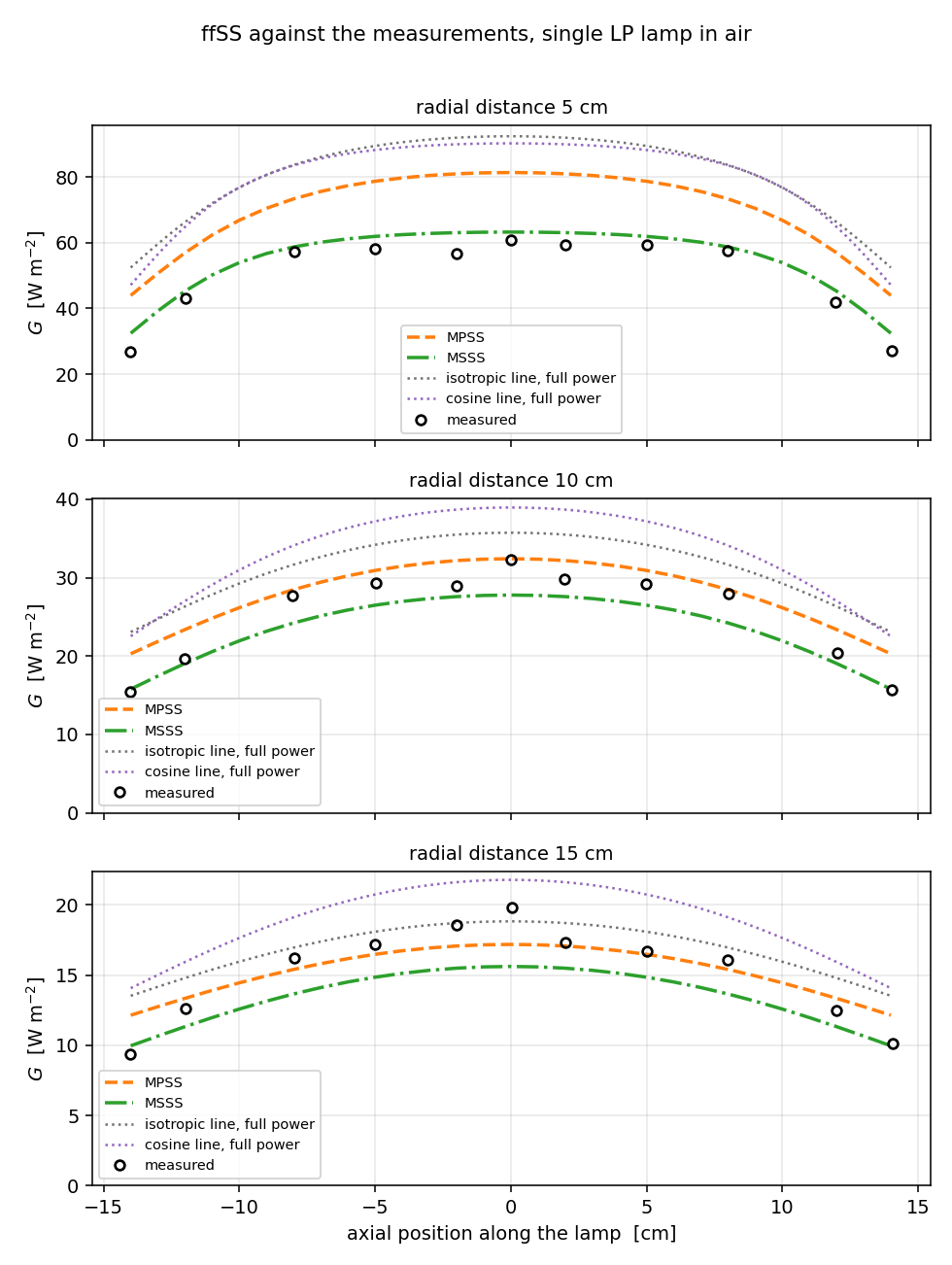
Values at the lamp mid-plane, in W/m².
| Radius | Measured | MPSS | MSSS |
|---|---|---|---|
| 5 cm | 60.83 | 81.32 (+33.7 %) | 63.22 (+3.9 %) |
| 10 cm | 32.29 | 32.43 (+0.4 %) | 27.79 (−13.9 %) |
| 15 cm | 19.81 | 17.18 (−13.3 %) | 15.61 (−21.2 %) |
Statistics over the full measurement lines (11 points per radius):
| Radius | Model | Mean signed error | Mean absolute error | R² |
|---|---|---|---|---|
| 5 cm | MPSS | +39.1 % | 39.1 % | −1.23 |
| 5 cm | MSSS | +8.3 % | 8.3 % | 0.91 |
| 10 cm | MPSS | +11.7 % | 11.7 % | 0.76 |
| 10 cm | MSSS | −7.1 % | 7.6 % | 0.81 |
| 15 cm | MPSS | +2.3 % | 9.0 % | 0.80 |
| 15 cm | MSSS | −10.7 % | 11.9 % | 0.54 |
The two models err in opposite directions because they see the lamp differently — MPSS as a
row of point sources on the axis, MSSS as a row of cylindrical surface elements radiating with a
cos θ weight. A point-source approximation looks brighter than the real cylinder as you
approach the lamp surface, and the cosine weighting in MSSS was introduced in the literature to
correct exactly that (paper p.393).
So MSSS suits near-lamp profile work and MPSS suits calculations that need absolute power. The R² of 0.91 at 5 cm and the power audit below show those two properties respectively.
Result 2 — power audit
A matching profile means the model has the right shape; it says nothing about how many watts go into the room. Integrating fluence rate over a sphere far enough away that the lamp looks like a point answers that question on its own.
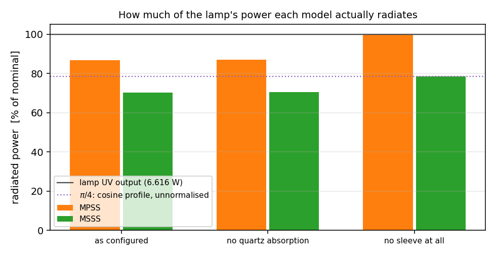
Sphere of radius 2 m, midpoint rule in μ = cos θ over 400 intervals, which never lands on a
pole:
| Model | As configured | Quartz absorption removed | Sleeve removed |
|---|---|---|---|
| MPSS | 5.738 W (86.7 %) | 5.757 W (87.0 %) | 6.620 W (100.05 %) |
| MSSS | 4.646 W (70.2 %) | 4.661 W (70.5 %) | 5.200 W (78.59 %) |
Against the nominal 6.616 W. This audit uses nothing from inside the models — it integrates the result field over a sphere — so it is evidence independent of the measurement comparison.
MPSS conserves. With the sleeve removed it reaches 100.05 %; what remains is the residual of 1000 segments and the spherical quadrature. The 13.3 % missing from the as-configured case is Fresnel reflection at the quartz interfaces, which is real physics — reflectance approaches 1 at grazing incidence. Quartz absorption accounts for only 0.3 %, because the sleeve is 1 mm thick.
MSSS radiates π/4 of the total by definition. With the sleeve removed it gives 78.59 %,
reproducing π/4 = 78.54 % to within 0.06 %. The cosine weighting is defined in the literature
without renormalisation (∫cos θ dΩ = π², not 4π), and UVSim3D implements the literature
definition as written — which also means its values are comparable with other UV design software
of the same lineage.
Where the inputs come from
This is a reproduction case, so the optical properties are the values the paper states.
Refractive indices — paper p.395 uses 1.0 for air, 1.52 for quartz and 1.38 for water (citing Bolton 2001). The configuration matches.
Reference path for sleeve transmittance — paper p.397 states that "T_w and T_q are the
10 mm path length transmittance of the water and quartz, respectively", and equation (13)
carries the exponent T_q^(d₂/0.01). Quartz therefore follows the same T₁₀ convention as water,
and so does the configuration. The 0.3 % quartz absorption above is a 10 mm-basis transmittance
of 0.97 applied over a 1 mm thickness.
Working from a vendor datasheet
A vendor quoting "97 % UVT" normally means transmittance through that sleeve, which is a different quantity from T₁₀. UVSim3D lets you state which path length a transmittance refers to, so enter the thickness it was measured over. See the configuration reference.
The measured values were read from Figure 7 of the paper above. The lamp specifications, refractive indices and measurement positions are all in the published literature, so this comparison can be checked independently.
References
- Liu, D., Ducoste, J., Jin, S., & Linden, K. (2004). Evaluation of alternative fluence rate distribution models. Journal of Water Supply: Research and Technology—AQUA, 53(6), 391–408.
- Bolton, J. R. (2000). Calculation of ultraviolet fluence rate distributions in an annular reactor: significance of refraction and reflection. Water Research, 34(13), 3315–3324.