
All three models compared against a single set of in-air measurements from Liu et al. (2004). Each model's individual validation is covered separately: the MPSS/MSSS measurement comparison and power audit, the DOM exact-solution check on an infinite diffuse cylinder, and the DOM enclosure benchmark from Fiveland (1984).
The conclusion first. The three models diverge substantially near the lamp, and the difference comes from what each takes the lamp to be rather than from numerical error. The DOM solver itself agrees with an exact solution to within about 1 %, so what follows is a property of the models.
Why they diverge
| Model | What it takes the lamp to be | Refraction |
|---|---|---|
| MPSS | a row of point sources on the axis | Snell and Fresnel computed per ray |
| MSSS | a row of cylindrical surface elements radiating as cos θ | computed per ray |
| DOM | a cylinder radiating diffusely from the sleeve surface | straight propagation (not represented) |
The discrete ordinates method advances along fixed directions in straight lines, so it does not carry the change of direction at an interface. That is a property of the method — commercial CFD DO models behave the same way. What it offers in exchange is solving a three-dimensional domain with absorption and scattering in one pass, which is exactly what a reactor interior is.
The DOM calculation uses the full 6.616 W lamp output as its source, without subtracting sleeve transmission losses, because no single coefficient can stand in for a transmittance that varies with angle. The DOM values below therefore do not include that loss. Fluence rate is linear in source power, so a transmittance can be applied to the results if needed.
Against the measurements
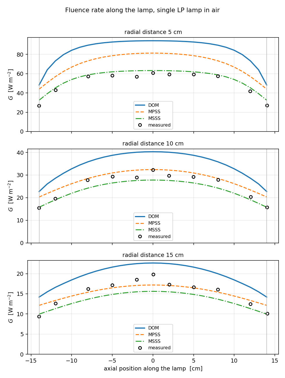
Values at the lamp mid-plane, in W/m².
| Radius | Measured | DOM | MPSS | MSSS |
|---|---|---|---|---|
| 5 cm | 60.83 | 94.15 (+54.8 %) | 81.32 (+33.7 %) | 63.22 (+3.9 %) |
| 10 cm | 32.29 | 40.32 (+24.9 %) | 32.43 (+0.4 %) | 27.79 (−13.9 %) |
| 15 cm | 19.81 | 22.64 (+14.3 %) | 17.18 (−13.3 %) | 15.61 (−21.2 %) |
They diverge close in and converge further out. The spread of +54.8 % / +33.7 % / +3.9 % at 5 cm becomes +14.3 % / −13.3 % / −21.2 % at 15 cm, mixed in sign and narrower, because the influence of refraction concentrates near the lamp surface.
The shape of the distribution — flat through the middle, falling away sharply at the arc ends — matches the measurements well for all three. What differs is magnitude.
This is the same trend the paper reports. Its conclusions state that DO "significantly over-predicts the fluence rate near the lamp surface" because it "did not incorporate the effects of refraction."
Which to use
| Purpose | Recommended |
|---|---|
| Fluence rate near the lamp surface (within about 5 cm) | MPSS or MSSS — refraction dominates here |
| Matching the shape of a measured profile | MSSS — R² 0.91 at 5 cm |
| Dose calculations needing absolute power conservation | MPSS — radiates 100.05 % |
| Reactor interiors where absorption dominates | DOM |
| Whole-field fluence in a multi-lamp reactor | DOM or MPSS |
The model is selected with solverConfig.radiationModel in the configuration file
("mpss" / "msss" / "dom").
This case leaves only refraction in play
The medium is air, so there is no absorption at all. In a real reactor, with water absorbing, attenuation takes over as distance from the lamp grows, and DOM accuracy in that regime is what the enclosure validation shows. Read the table above as the most demanding condition for DOM.
All three were computed for the same lamp configuration at the same measurement points. The lamp specifications and measurement conditions are published in the paper below.
References
- Liu, D., Ducoste, J., Jin, S., & Linden, K. (2004). Evaluation of alternative fluence rate distribution models. Journal of Water Supply: Research and Technology—AQUA, 53(6), 391–408.
- Akehata, T., & Shirai, T. (1972). Effect of light-source characteristics on the performance of circular annular photochemical reactor. Journal of Chemical Engineering of Japan, 5(4), 385–391.